Edge makes a nice indicator holder for the lathe that fits a QCTP. Now that I have a QCTP I decided to make a holder that mimics the Edge holder. A piece of 3/8" aluminum was cut to a 2.75" square. A matching piece of 3/8" steel was found that is 3/4" X 2.75". The indicator was measured at 2.165". A 2.4" circle was laid out off center on the aluminum. Indents were also laid out on two adjacent corners, but were never used.
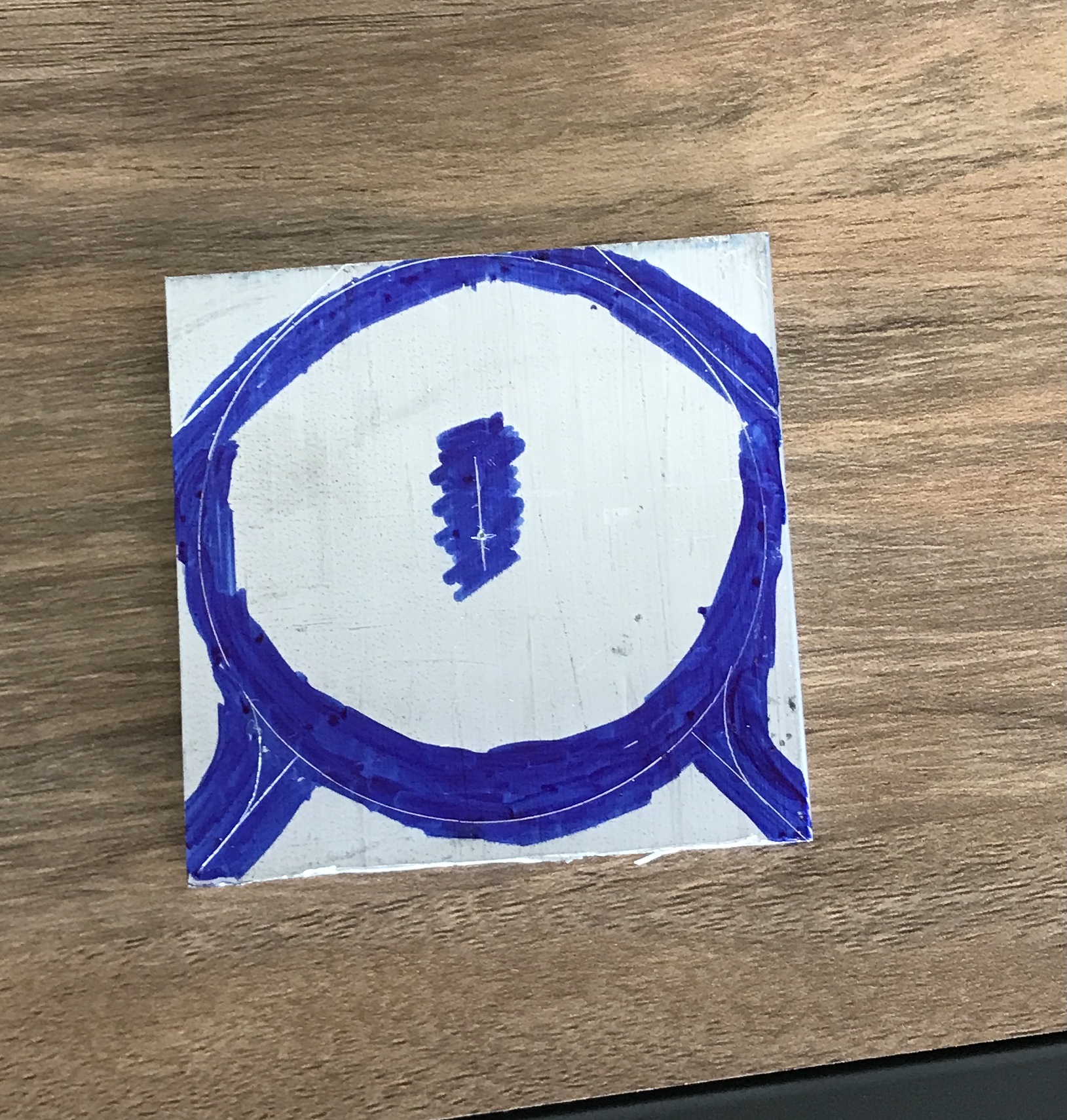
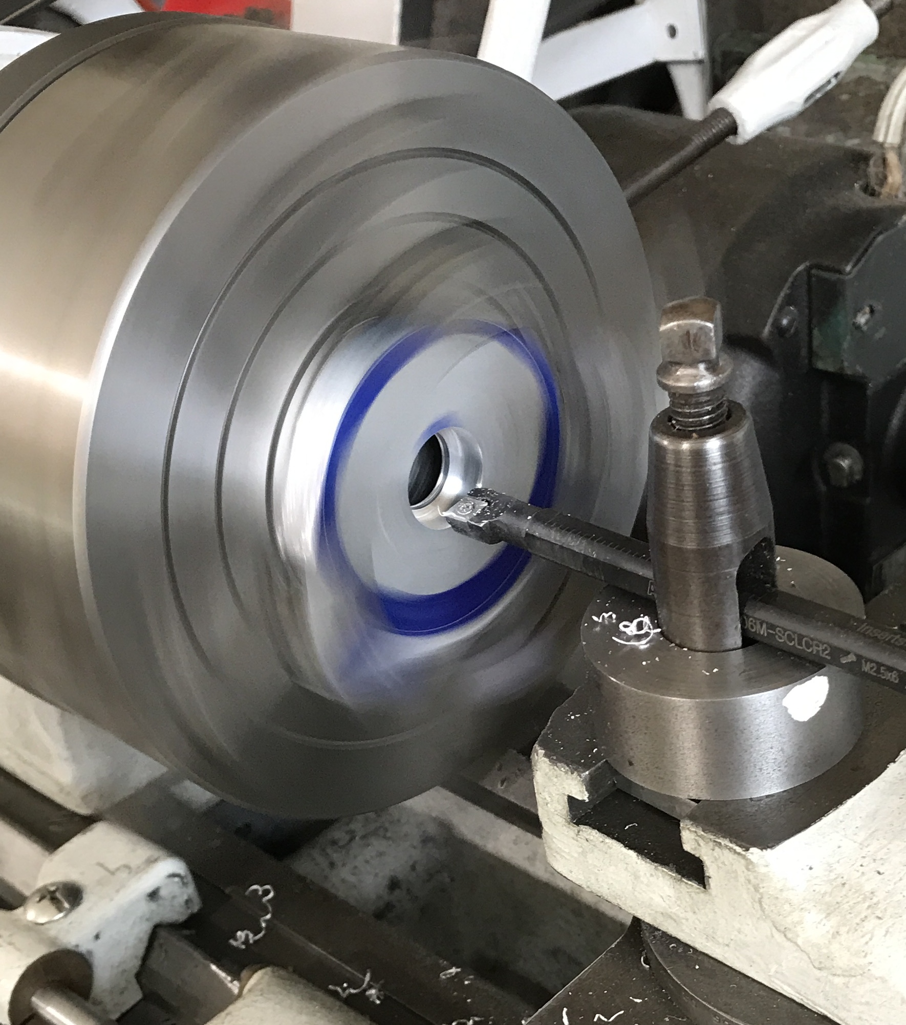
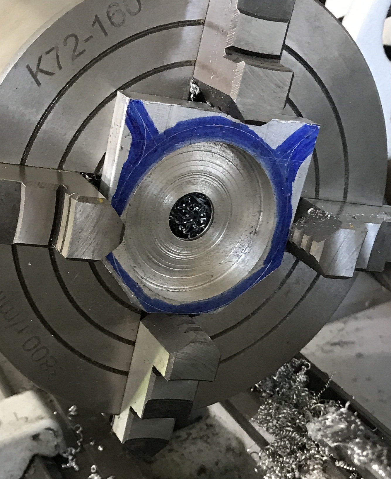
The two smallest corners were cut off with the hack saw. A hole was drilled through the aluminum up to 1/2". This hole was bored to 5/8" to accomodate the tab on the back of the indicator. The hole was then bored to 2.166" to fit the 2.165" indicator. This boring did not go through and left about 1/16" of material on the back.
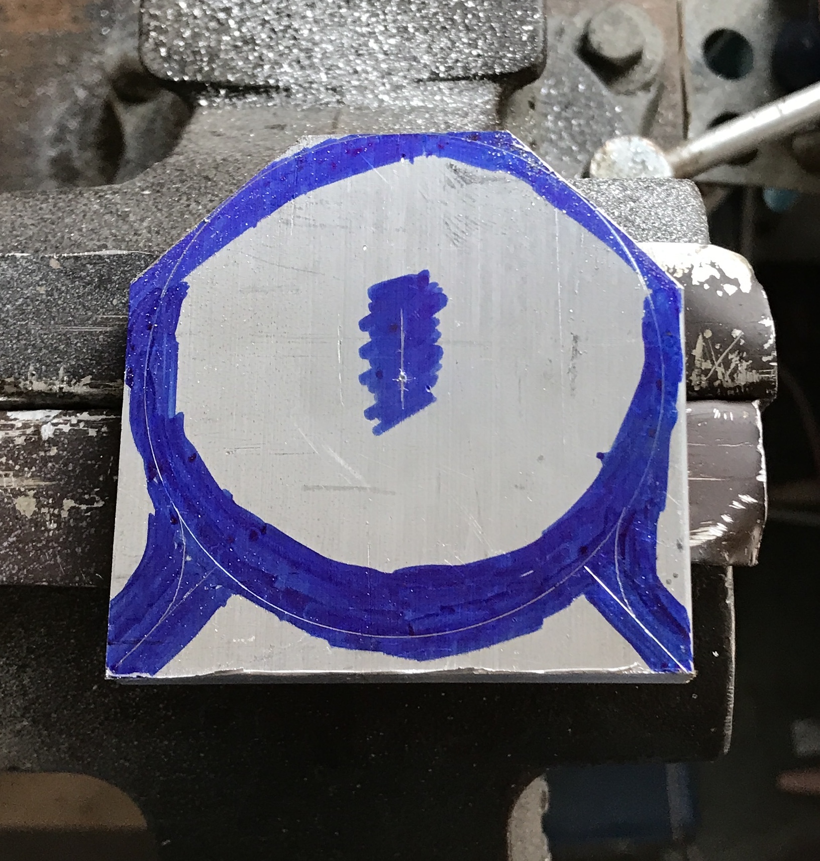
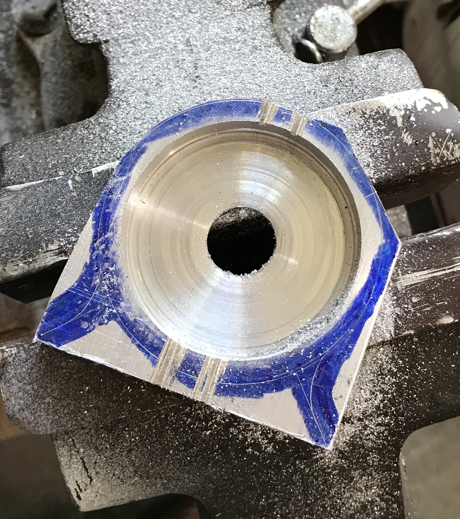
The outside work came next. The first corner was rounded with a file over a twenty minute period. It was quite exhausting. After lunch I used the sanding belt. This did a better job and took only about five minutes with minimal effort. The correct slots were cut for the indicator pin on the table saw about 3/16" deep.
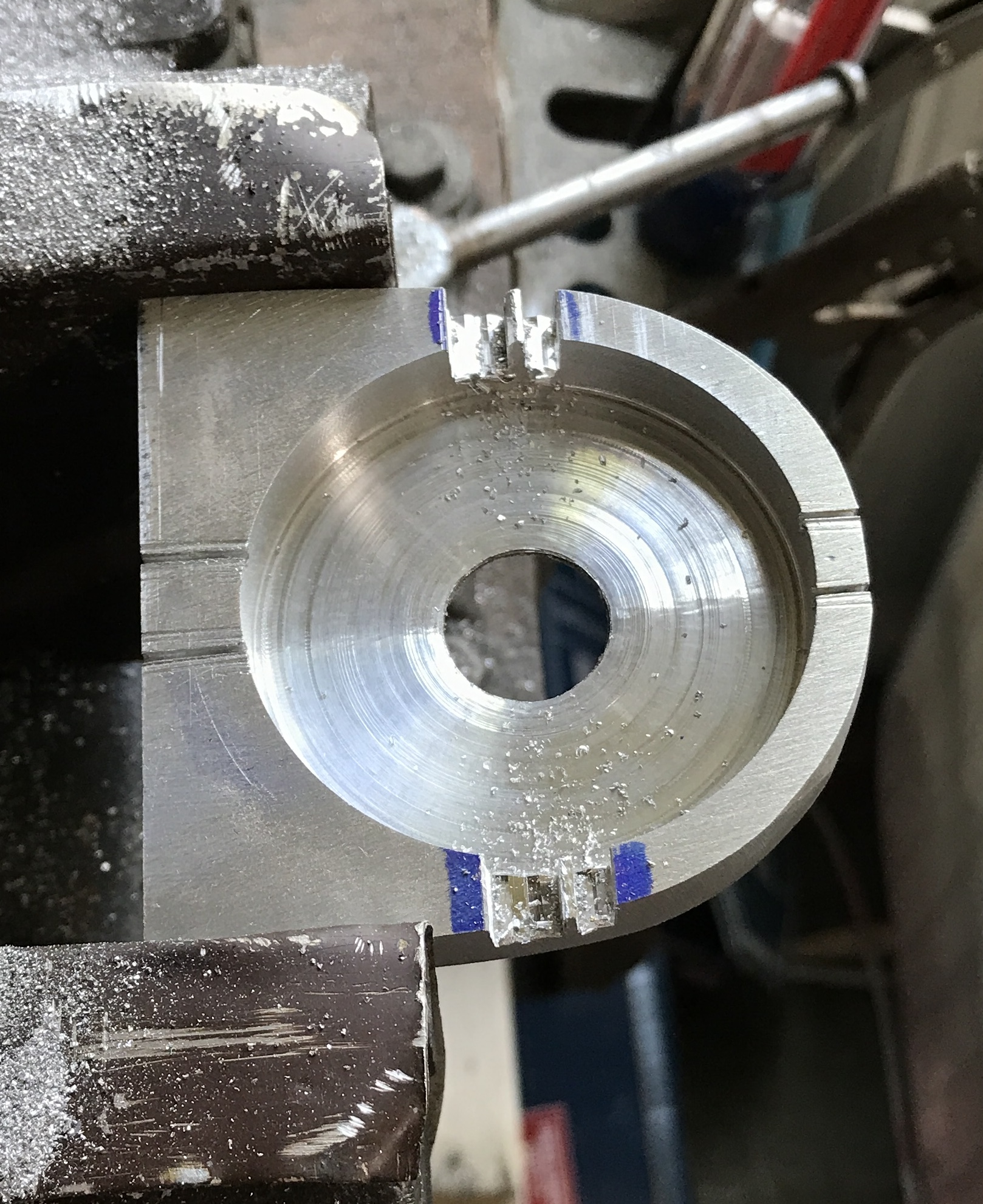
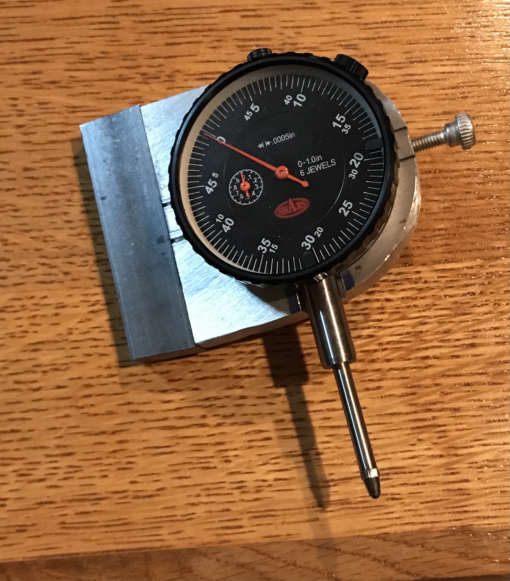
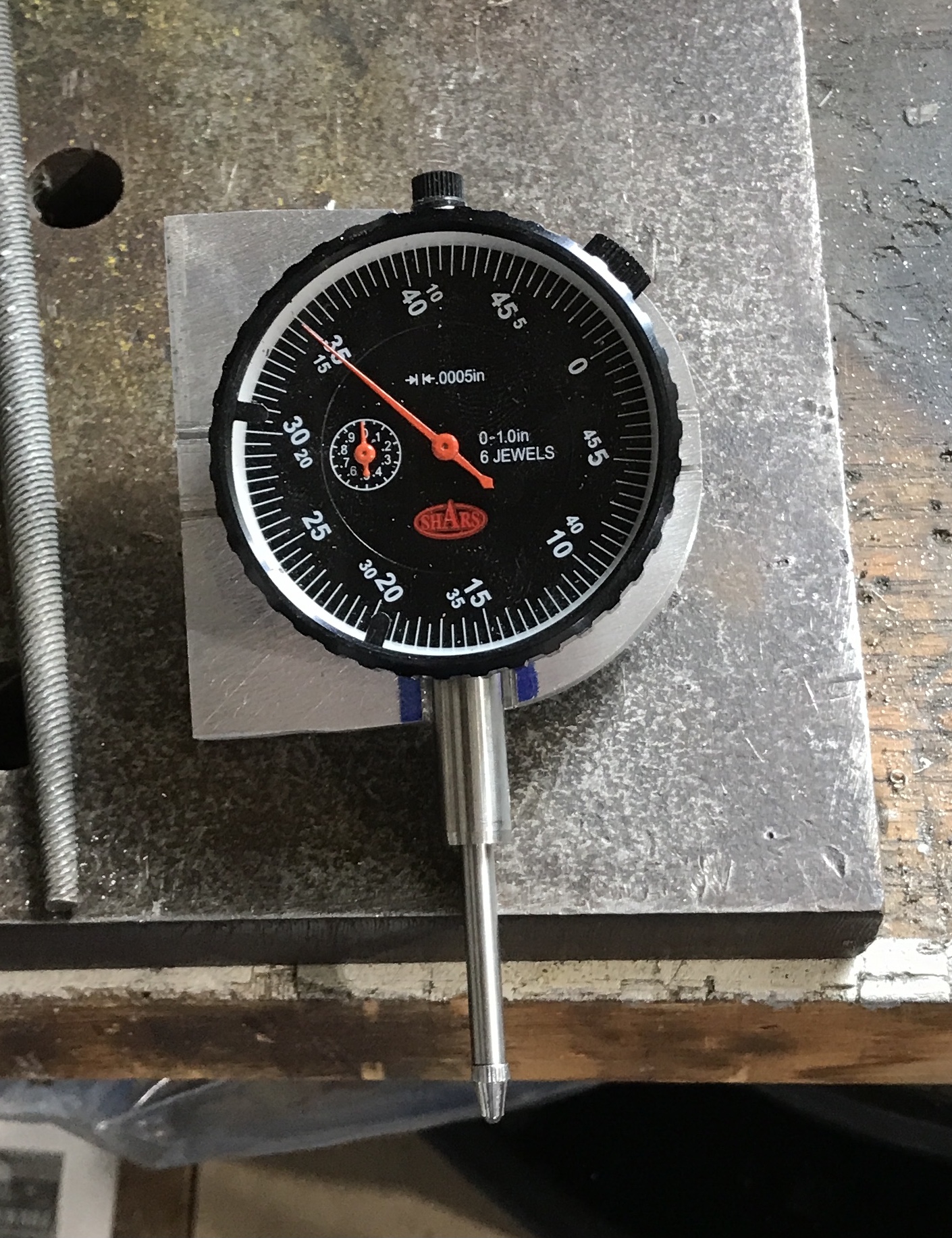
The waste in the slots was removed with a round file. The indicator nestled firmly in the holder as seen in the photo below. The holder was cleaned up by sanding and the edges were chamfered.
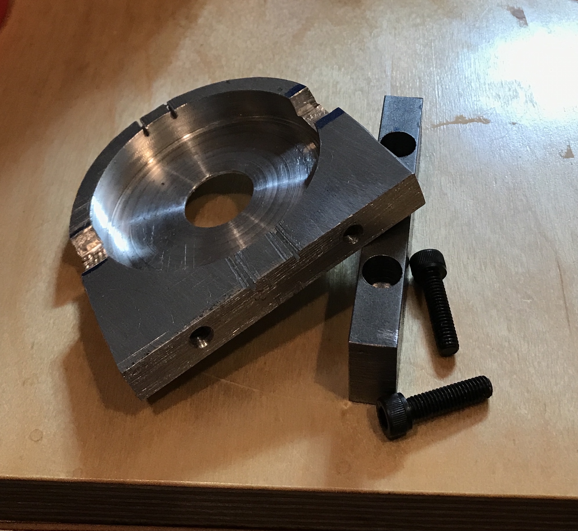
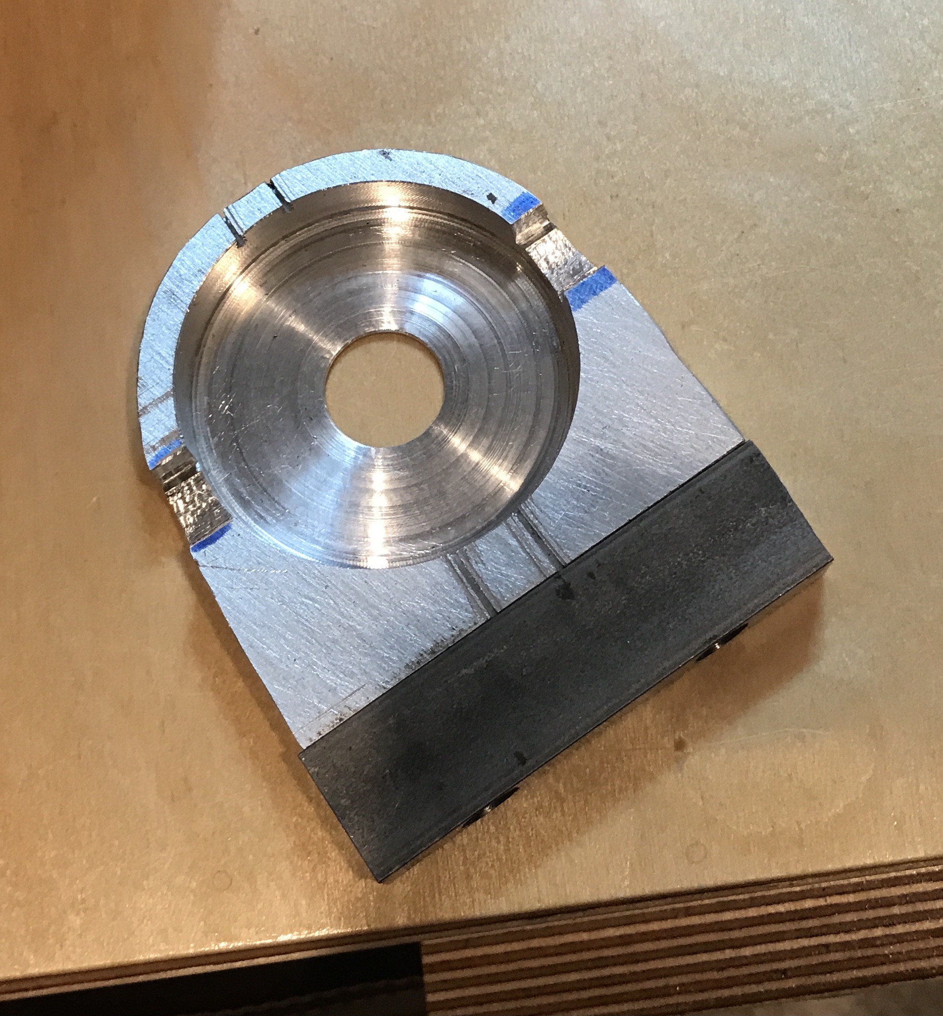
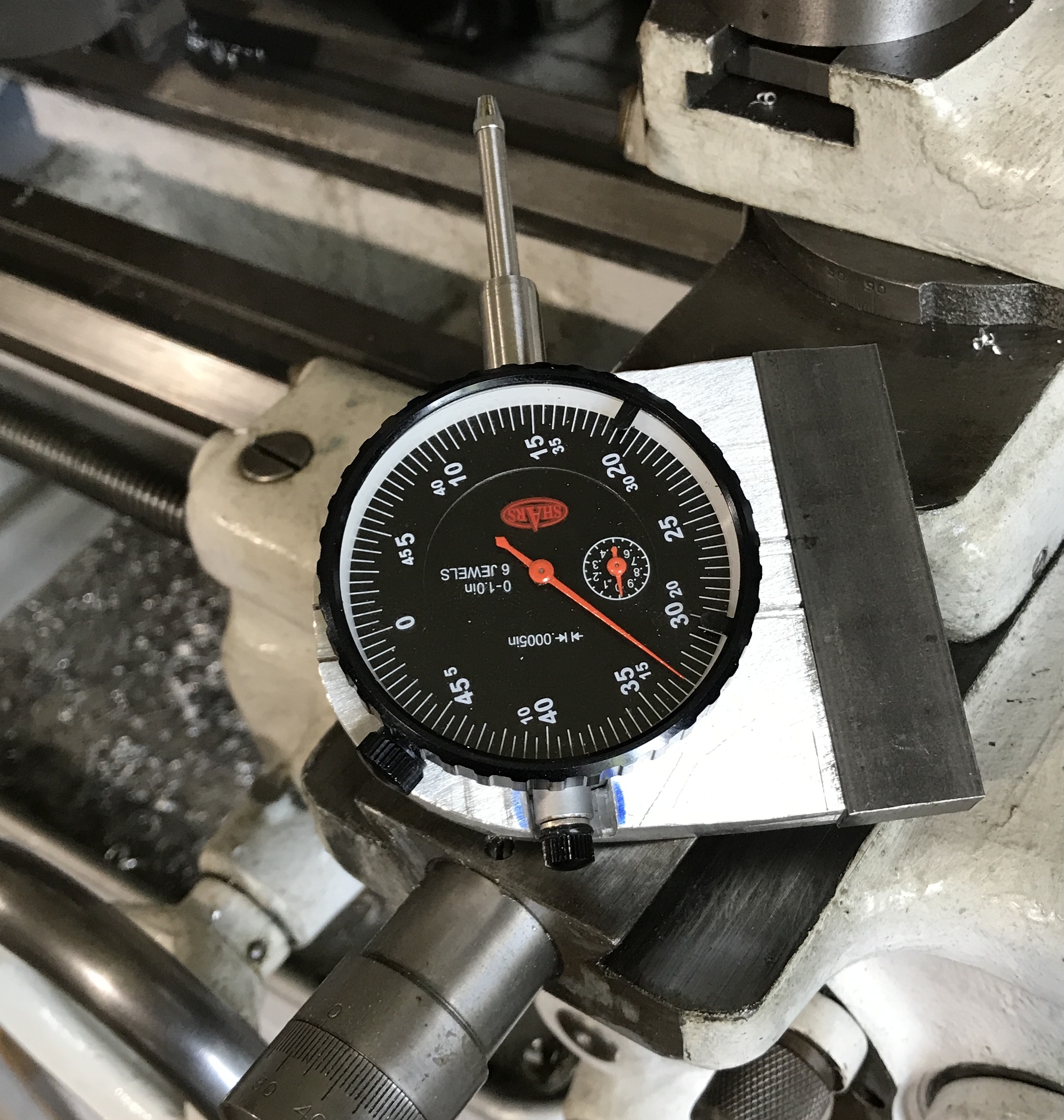
Two screws were used to hold the two parts together. The steel was marked 5/8" in from the ends and the center of the 3/8" edge was marked. Punch marks were made at both of these locations. A center drill was used to start the holes. The holes were drilled through for a 10-32 screw using a 7/32" drill in the drill press. The holes were opened to fit the socket head with a 5/16" drill to a 3/8" depth. The holes were transferred to the aluminum holder. These holes were center drilled, drilled 3/4" deep with a #21 drill, and tapped 10-32. The holes were cleaned out with compressed air. The first photo shows the completed parts and the second shows the assembled indicator holder. Last but not least is a photo of the holder with indicator 'mounted' on the lathe.
The indicator rotates freely in the holder as the slots were made too wide. This will need to be corrected somehow.
A nice 8-32 set screw was discovered. A hole was drilled in the side of the housing with a #29 drill. It was tapped 8/32. After deburring the hole the lightly filed set screw was installed. The photo below shows the completed indicator holder.